
A sump pump vertical float switch is an automatic control device that activates your basement pump when rising water lifts a buoyant float along a fixed vertical rod. This simple mechanical trigger prevents flooding without requiring manual intervention or complex electronics. Most residential models operate on standard 120V circuits and handle up to 1/2 horsepower motors as of 2026.
Understanding this component helps you troubleshoot issues or plan a reliable replacement before the next heavy rain hits.
what is a sump pump vertical float switch
A sump pump vertical float switch triggers automatic pump activation via rising water levels. The buoyant float slides upward along a fixed vertical guide rod. Internal electrical contacts close at a preset height threshold.
This completes the circuit to start the submersible motor immediately. The mechanism requires no external power source for sensing.
What a Sump Pump Vertical Float Switch Actually Does
This device serves one critical purpose in your waterproofing system. It acts as the brain that tells the pump when to run based solely on water level. Without it, you would need to manually monitor the pit during every storm or risk severe basement damage.
The switch eliminates guesswork by providing consistent activation points. Water rises until the float reaches the "on" position, triggering the motor instantly. Once the water drops back down, the float descends and cuts power to prevent dry running.
This cycle repeats automatically whenever groundwater accumulates in the basin.
Reliability matters more than complexity here. Mechanical vertical switches work even if smart home systems fail or Wi-Fi goes out. They provide a baseline safety net that protects your foundation year-round.
Many homeowners pair them with diagnostic troubleshooting guides for other appliances to create a comprehensive home maintenance strategy.
How It Works and Key Parts Inside
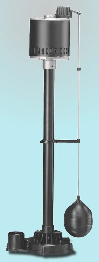
Image source: Wikimedia Commons / Own work (CC BY-SA)
The internal mechanism relies on gravity and buoyancy rather than sensors. A hollow plastic or foam float slides freely up and down a stationary metal or PVC rod mounted inside the pit. As water fills the basin, hydrostatic force pushes the float upward against minimal friction.
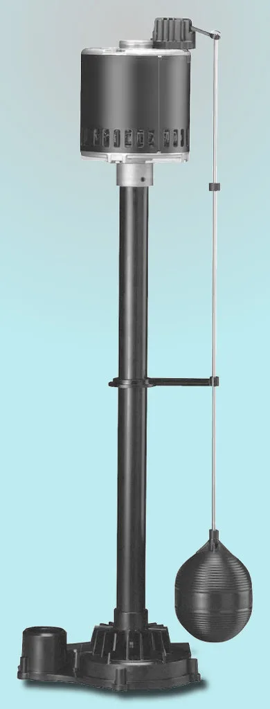
Image source: Wikimedia Commons / Own work (CC BY-SA)
Inside the switch housing, a pivoting lever connects to electrical contacts. When the float hits the activation point, it tilts the lever to close the circuit. This sends current directly to the pump motor through sealed wiring connections.
The National Electrical Code requires GFCI protection for all sump pump receptacles to prevent shock hazards near standing water.
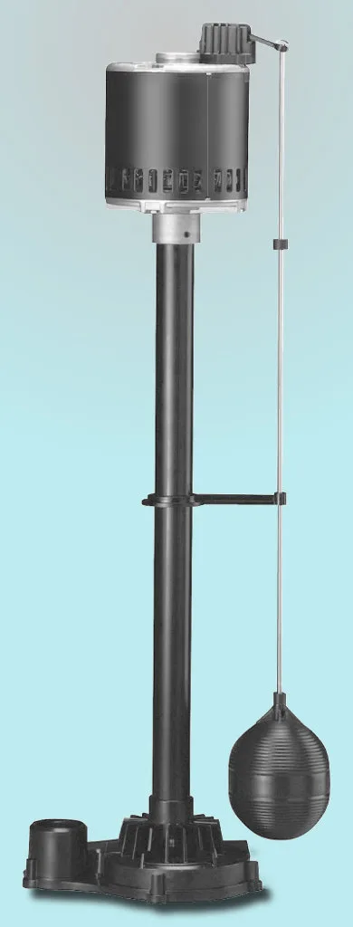
Image source: Wikimedia Commons / Own work (CC BY-SA)
Debris is the primary enemy of smooth operation. Sand, gravel, or stringy roots can jam the float against the guide rod. Regular inspection ensures nothing obstructs the travel path between off and on positions.
You should also verify that tether cords have enough slack but won't tangle around discharge pipes during cycling.
Installing, Replacing, and Maintaining One Yourself
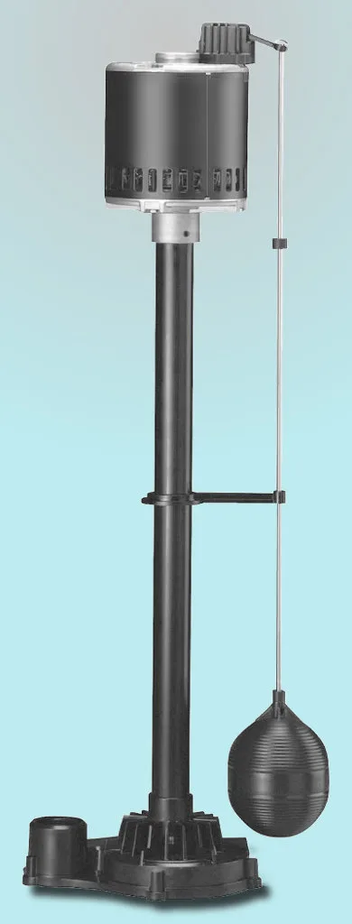
Image source: Wikimedia Commons / Own work (CC BY-SA)
Proper installation starts with positioning the switch correctly above the pump intake. Mount the bracket so the float activates when water covers the pump volute but stays below floor level. Setting it too low causes short cycling while setting it too high risks overflow before engagement.
Wiring must match manufacturer specifications exactly. Connect the switch leads to the pump cord using waterproof wire nuts rated for wet locations. Never splice wires inside the pit where condensation can corrode connections over time.
Always test the GFCI outlet after installation to confirm ground fault protection functions properly.
Maintenance involves quarterly visual checks and annual cleaning. Remove sediment buildup from the guide rod using a soft brush and mild detergent. Inspect the float for cracks or waterlogging that could alter buoyancy characteristics.
If you notice erratic behavior despite clean components, consult error code resources to rule out electrical faults elsewhere in the system.
Replacement follows the same steps in reverse order. Disconnect power at the breaker before unmounting the old assembly. Match the new switch voltage and amperage ratings to your existing pump specifications.
Document the original mounting height to avoid recalibrating activation levels during reinstallation.
Vertical Float Switch vs Other Sump Pump Switch Types
Choosing the right switch type depends on your specific pit configuration and reliability needs. Vertical floats excel in narrow basins where horizontal swing space is limited. They resist tangling better than tethered models since movement stays constrained to a single axis.
| Feature | Vertical Float | Horizontal Tether | Electronic Sensor |
|---|---|---|---|
| Space Required | Minimal width | Wide swing arc | Compact probe |
| Debris Resistance | Moderate | Low | High |
| Adjustment Ease | Fixed bracket | Tie length varies | Digital settings |
| Failure Mode | Mechanical jam | Cord entanglement | Circuit board failure |
| Typical Lifespan | 5 to 7 years | 3 to 5 years | 7 to 10 years |
Horizontal switches cost less upfront but require wider pits to function reliably. The floating bulb swings outward on a cord, making it prone to snagging on pipes or debris. Electronic sensors offer precision adjustment but introduce circuit boards that can fail during power surges.
For most standard residential installations, vertical switches balance durability with space efficiency effectively.
Some modern systems integrate multiple switch types for redundancy. A primary vertical float handles routine cycling while an electronic backup monitors extreme events. This layered approach mirrors how professionals approach appliance error diagnosis by checking mechanical and electrical systems separately.
Redundancy provides peace of mind in flood-prone regions where pump failure carries catastrophic consequences.
Frequently Asked Questions About Vertical Float Switches
Can I adjust the activation height on a vertical float switch?
Most vertical switches feature adjustable brackets or set screws for fine-tuning. Loosen the mounting hardware and slide the assembly up or down the guide rod. Retighten securely after testing the new water level with a garden hose.
Avoid setting activation below the pump intake to prevent air locking and motor burnout.
Why does my vertical float switch keep getting stuck?
Debris accumulation is the most common cause of sticking floats. Clean the guide rod and float interior thoroughly during each maintenance visit. Check for mineral deposits from hard water that create friction points.
Replace worn bushings or cracked floats immediately since damaged components rarely self-correct through cleaning alone.
Do vertical float switches work with pedestal pumps?
Yes, many universal vertical switches mount to pedestal pump columns or separate brackets. Verify voltage compatibility before purchasing since pedestal motors often use different amperage ratings than submersibles. Ensure adequate clearance between the float travel zone and the pedestal base plate.
Some manufacturers sell dedicated pedestal conversion kits for guaranteed fitment.
How long should a vertical float switch last before replacement?
Quality mechanical switches typically survive five to seven years under normal residential use. Harsh conditions like sandy soil or frequent cycling may shorten lifespan significantly. Watch for symptoms like delayed activation, chattering contacts, or visible corrosion on terminals.
Proactive replacement every five years prevents emergency failures during peak storm seasons.
Is professional installation required for vertical float switches?
DIY installation is acceptable if you understand basic electrical safety and local codes. However, hiring a licensed electrician ensures compliance with NEC grounding and GFCI requirements. Professional installers also optimize switch placement for your specific pit geometry.
Consider expert help if your system includes battery backups or dual-pump configurations that add wiring complexity.