
Knowing how to test a sump pump float switch prevents basement flooding and costly motor burnout. Most failures stem from debris jams or worn electrical contacts rather than total pump failure.
Manufacturer specifications indicate most residential switches operate on 115V circuits with 4 to 10 amp draws. The National Electrical Code requires GFCI protection for these outlets to prevent shock hazards during inspection. Let’s get your system checked safely.
How to Test a Sump Pump Float Switch
Unplug the sump pump before testing any float switch components. Manually lift the float arm to verify smooth mechanical movement without binding. Use a multimeter set to ohms to check electrical continuity at the plug prongs.
A reading near zero ohms confirms the internal contacts are closed and functional. Reconnect power only after verifying the switch activates correctly.
Safety First: Power Isolation and Switch Identification
Why You Must Unplug Before Testing
Water and electricity create lethal conditions in sump pits. Always disconnect the piggyback plug from the GFCI outlet before reaching into the basin. Even low-voltage electronic sensors can fail dangerously if water breaches sealed housings.
Treat every component as live until physically unplugged.
Wet hands or damp floors increase conductivity risks significantly. Wear rubber-soled shoes and insulated gloves when working near standing water. If the outlet lacks GFCI protection, shut off the circuit breaker instead.
Never bypass safety devices to speed up diagnostics.
Identifying Your Switch Type: Tethered, Vertical, or Electronic
Tethered floats hang freely on a cord and pivot around a fixed point. Vertical slides move up and down a stationary rod inside the pit. Electronic sensors have no moving parts and detect water through conductivity probes.
Each type requires different testing approaches and adjustment methods.
Check the manufacturer label or housing shape if identification is unclear. Tethered models typically have adjustable cord lengths via clamp screws. Vertical units often feature set screws limiting travel distance.
Electronic versions usually include LED status indicators on the control module.
Misidentifying your switch leads to incorrect diagnostic steps. Forcing a vertical slide sideways can crack the guide rod permanently. Testing continuity on sealed electronic units yields meaningless readings.
Match your physical hardware to the correct workflow branch below.
The Diagnostic Workflow: Manual Lift vs. Multimeter Test
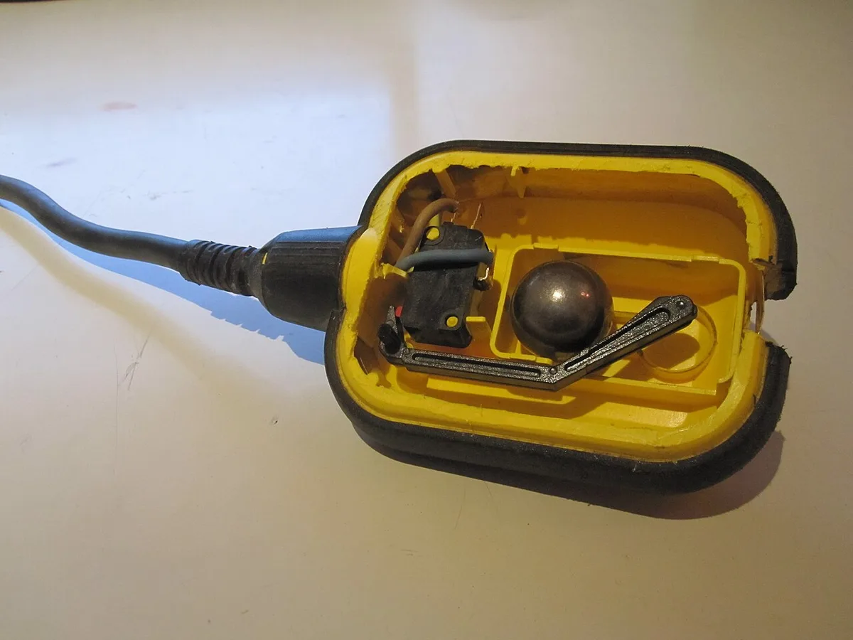
Image source: Wikimedia Commons / Martin Meise (CC BY)
Branch 1: Testing Mechanical Floats (Tethered & Vertical)
Mechanical switches rely on gravity and buoyancy to trigger internal microswitches. Lift the float slowly by hand while listening for an audible click. Resistance or grinding indicates mineral scale buildup or debris interference.
Clean the pivot points with white vinegar if movement feels sticky.
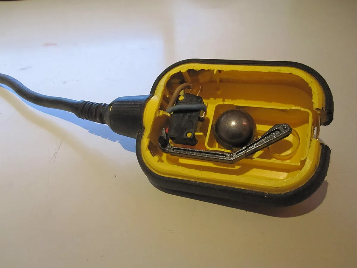
Image source: Wikimedia Commons / Martin Meise (CC BY)
Verify the float returns fully to its resting position when released. Incomplete return suggests tether tangling or rod corrosion. Inspect the buoyant bulb for cracks that allow water ingress.
A waterlogged float loses lifting force and fails prematurely.
Adjust tether length if activation height seems wrong. Shorter tethers raise the turn-on point while longer ones lower it. Secure adjustments tightly to prevent slippage during operation.
Retest manually after every adjustment to confirm proper range.
Branch 2: Testing Electronic Sensors and Sealed Units
Electronic sensors lack user-serviceable internal components. Visual inspection focuses on probe cleanliness and wiring integrity. Wipe sensing rods with isopropyl alcohol to remove biofilm or sediment.
Corroded terminals require replacement rather than cleaning.
Test upstream voltage at the control module input terminals. Absence of expected voltage points to wiring faults before the sensor. Presence of correct voltage with no pump activation confirms sensor failure.
These units rarely fail intermittently so binary pass/fail results are reliable.
Avoid submerging control modules unless rated for underwater use. Moisture intrusion destroys solid-state circuitry instantly. Verify IP ratings match your installation environment before reassembly.
Replace entire assemblies rather than attempting board-level repairs.
Interpreting Multimeter Readings for NO vs. NC Contacts
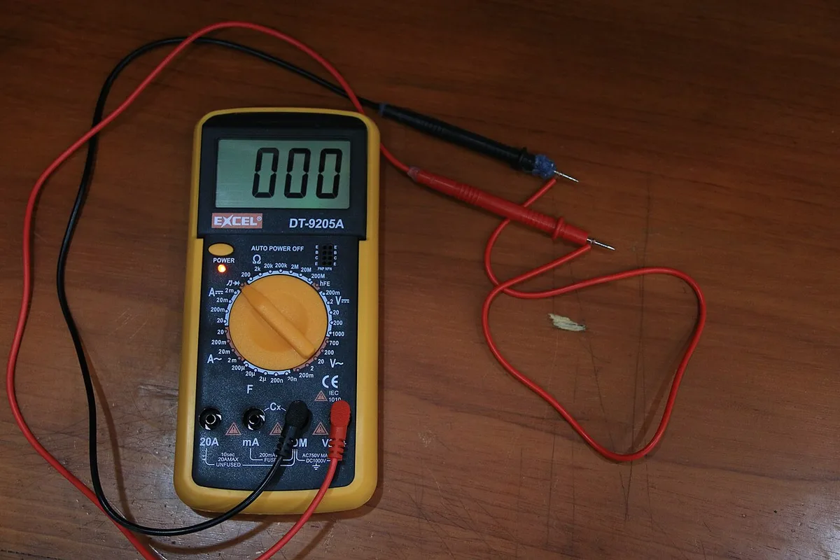
Image source: Wikimedia Commons / MinhVN123
Normally open switches show infinite resistance when the float rests down. Lifting the float should drop resistance below one ohm. Normally closed switches display the opposite behavior pattern.
Check manufacturer documentation or housing markings to confirm contact configuration.
Inconsistent readings suggest arcing damage inside sealed contacts. Intermittent connectivity causes short cycling and motor stress. Replace switches showing fluctuating values even if they occasionally work.
Internal pitting worsens rapidly once contact degradation begins.
Use alligator clips to maintain steady probe contact during testing. Handheld probes introduce variable pressure affecting measurements. Record baseline readings for future comparison during routine maintenance.
Significant deviation from original specs predicts impending failure.
Troubleshooting Failures: Stuck Switches, Short Cycling, and Burnout
Fixing Debris Jams and Mineral Scale Buildup
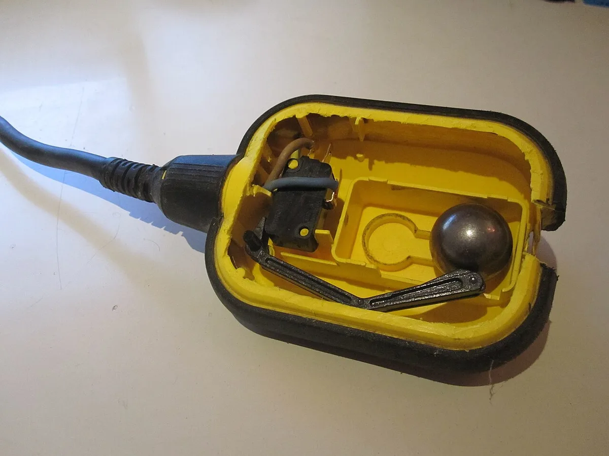
Image source: Wikimedia Commons / Martin Meise (CC BY)
Gravel, roots, and iron ochre commonly immobilize mechanical floats. Remove visible obstructions from the pit bottom first. Soak crusty deposits in undiluted white vinegar for thirty minutes.
Scrub gently with a nylon brush to avoid damaging plastic surfaces.
Hard water regions accelerate calcium carbonate accumulation on moving parts. Install inline water softeners if scale recurs within months. Rinse cleaned components thoroughly before reinstallation.
Residual acid continues corroding metal fasteners over time.
Prevent future jams by installing pit covers or inlet screens. Regular quarterly inspections catch minor buildup before complete seizure. Document cleaning dates to establish local maintenance intervals.
Environmental conditions vary widely between geographic regions.
Adjusting Tether Length to Stop Short Cycling
Rapid on-off cycling burns out pump motors prematurely. Turbulent water bouncing the float causes false triggers. Lengthen the tether slightly to increase activation differential.
This adds hysteresis preventing immediate shutoff after startup.
Ensure adequate clearance between float and pit walls. Tight spaces create suction effects disrupting natural movement. Reposition discharge pipes deflecting water toward the switch.
Baffles or stilling wells reduce surface agitation effectively.
Test adjustments using actual water rather than manual lifting. Pour five gallons directly into the pit observing cycle timing. Ideal run times exceed ten seconds minimum per activation.
Faster cycling indicates further tuning remains necessary.
When to Repair vs. Replace the Float Switch
Minor cleaning resolves most intermittent operation issues cheaply. Physical damage like cracked housings demands full replacement. Electrical contact wear shows as progressive unreliability despite cleaning.
Age exceeding seven years justifies proactive replacement regardless of current function.
Universal aftermarket switches cost less than OEM equivalents typically. Verify amperage and voltage ratings match original specifications exactly. Underrated replacements melt internally under load creating fire hazards.
Overrated units may lack sensitivity for low-flow applications.
Consider upgrading switch technology during replacement cycles. Electronic sensors eliminate mechanical wear points entirely. Vertical slides resist tangling better than tethered designs in cramped pits.
Evaluate long-term reliability versus upfront cost tradeoffs carefully.
Common Testing Mistakes and Sump Pump FAQs
Critical Errors That Damage Pumps or Risk Shock
Testing live circuits without proper PPE invites electrocution injury. Water conducts fault currents through tools and bodies easily. Assuming GFCI outlets guarantee safety ignores device failure possibilities.
Always verify de-energization with a non-contact voltage tester first.
Forcing stuck mechanisms breaks plastic pivots irreparably. Patience and solvent soaking free seized components safely. Ignoring manufacturer torque specs strips adjustment screws during reassembly.
Cross-threaded fittings leak water onto electrical connections later.
Skipping functional re-tests leaves problems undiscovered until flooding occurs. Verify operation multiple times across different water levels. Monitor performance over several days post-repair for latent issues.
Confidence comes from repeated successful validation not single checks.
Frequently Asked Questions About Float Switch Testing
How often should I test my sump pump float switch?
Test functionality every three to four months as standard practice. Increase frequency to monthly during wet seasons or high water table periods. Annual professional inspections complement homeowner testing routines effectively.
Consistent verification catches degradation before catastrophic failure occurs.
Can I replace just the float switch without replacing the pump?
Yes, most switches connect via standardized piggyback plugs allowing independent replacement. Ensure new switch amperage matches pump motor requirements precisely. Hardwired installations require qualified electricians for safe disconnection and reconnection.
Separate component replacement saves significant money versus full unit swaps.
Why does my sump pump keep turning on and off rapidly?
Short cycling usually indicates turbulent water disturbing float stability or incorrect tether length. Adjusting activation differential adds necessary hysteresis between cycles. Check valve failures also cause backflow triggering immediate restarts.
Diagnose root cause before adjusting switch settings blindly.
What tools do I need to test a sump pump float switch?
A digital multimeter with continuity setting handles electrical verification adequately. Basic hand tools suffice for mechanical adjustments and cleaning tasks. Non-contact voltage testers confirm safe de-energization before touching components.
Rubber gloves and eye protection complete essential personal safety equipment.